|
INTRODUCTION
Induction motors are the most widely used motors for
appliances, industrial control, and automation; hence,
they are often called the workhorse of the motion indus-
try. They are robust, reliable, and durable. When power
is supplied to an induction motor at the recommended
specifications, it runs at its rated speed. However,
many applications need variable speed operations. For
example, a washing machine may use different speeds
for each wash cycle. Historically, mechanical gear sys-
tems were used to obtain variable speed. Recently,
electronic power and control systems have matured to
allow these components to be used for motor control in
place of mechanical gears. These electronics not only
control the motor’s speed, but can improve the motor’s
dynamic and steady state characteristics. In addition,
electronics can reduce the system’s average power
consumption and noise generation of the motor.
Induction motor control is complex due to its nonlinear
characteristics. While there are different methods for
control, Variable Voltage Variable Frequency (VVVF) or
V/f is the most common method of speed control in
open loop. This method is most suitable for applica-
tions without position control requirements or the need
for high accuracy of speed control. Examples of these
applications include heating, air conditioning, fans and
blowers. V/f control can be implemented by using low
cost PICmicro? microcontrollers, rather than using
costly digital signal processors (DSPs).
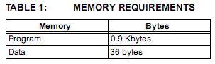
Many PICmicro microcontrollers have two hardware
PWMs, one less than the three required to control a
3-phase induction motor. In this application note, we
will generate a third PWM in software, using a general
purpose timer and an I/O pin resource that are readily
available on the PICmicro microcontroller. This applica-
tion note also covers the basics of induction motors and
different types of induction motors.
Induction Motor Basics
NAMEPLATE PARAMETERS
A typical nameplate of an induction motor lists the
following parameters:
• Rated terminal supply voltage in Volts
• Rated frequency of the supply in Hz
• Rated current in Amps
• Base speed in RPM
• Power rating in Watts or Horsepower (HP)
• Rated torque in Newton Meters or Pound-Inches
• Slip speed in RPM, or slip frequency in Hz
• Winding insulation type - Class A, B, F or H
• Type of stator connection (for 3-phase only), star
(Y) or delta (?)
When the rated voltage and frequency are applied to
the terminals of an induction motor, it draws the rated
current (or corresponding power) and runs at base
speed and can deliver the rated torque.
MOTOR ROTATION
When the rated AC supply is applied to the stator wind-
ings, it generates a magnetic flux of constant magni-
tude, rotating at synchronous speed. The flux passes
through the air gap, sweeps past the rotor surface and
through the stationary rotor conductors. An electro-
motive force (EMF) is induced in the rotor conductors
due to the relative speed differences between the rotat-
ing flux and stationary conductors.
The frequency of the induced EMF is the same as the
supply frequency. Its magnitude is proportional to the
relative velocity between the flux and the conductors.
Since the rotor bars are shorted at the ends, the EMF
induced produces a current in the rotor conductors.
The direction of the rotor current opposes the relative
velocity between rotating flux produced by stator and
stationary rotor conductors (per Lenz's law).
To reduce the relative speed, the rotor starts rotating in
the same direction as that of flux and tries to catch up
with the rotating flux. But in practice, the rotor never
succeeds in 'catching up' to the stator field. So, the
rotor runs slower than the speed of the stator field. This
difference in speed is called slip speed. This slip speed
depends upon the mechanical load on the motor shaft.
Note: Refer to Appendix C for glossary of
technical terms.
Author: Padmaraja Yedamale
Microchip Technology Inc.
The frequency and speed of the motor, with respect to
the input supply, is called the synchronous frequency
and synchronous speed. Synchronous speed is
directly proportional to the ratio of supply frequency
and number of poles in the motor. Synchronous speed
of an induction motor is shown in Equation 1.
EQUATION 1:
Synchronous speed is the speed at which the stator
flux rotates. Rotor flux rotates slower than synchronous
speed by the slip speed. This speed is called the base
speed. The speed listed on the motor nameplate is the
base speed. Some manufacturers also provide the slip
as a percentage of synchronous speed as shown in
Equation 2.
EQUATION 2:
INDUCTION MOTOR TYPES
Based on the construction of the rotor, induction motors
are broadly classified in two categories: squirrel cage
motors and slip ring motors. The stator construction is
the same in both motors.
Squirrel Cage Motor
Almost 90% of induction motors are squirrel cage
motors. This is because the squirrel cage motor has a
simple and rugged construction. The rotor consists of a
cylindrical laminated core with axially placed parallel
slots for carrying the conductors. Each slot carries a
copper, aluminum, or alloy bar. If the slots are semi-
closed, then these bars are inserted from the ends.
These rotor bars are permanently short-circuited at
both ends by means of the end rings, as shown in
Figure 1. This total assembly resembles the look of a
squirrel cage, which gives the motor its name. The rotor
slots are not exactly parallel to the shaft. Instead, they
are given a skew for two main reasons:
a) To make the motor run quietly by reducing the
magnetic hum.
b) To help reduce the locking tendency of the rotor.
Rotor teeth tend to remain locked under the sta-
tor teeth due to direct magnetic attraction
between the two. This happens if the number of
stator teeth are equal to the number of rotor
teeth.
Note 1: The number of poles is the number of
parallel paths for current flow in the stator.
2: The number of poles is always an even
number to balance the current flow.
3: 4-pole motors are the most widely used
motors.
Synchronous Speed (Ns) = 120 x F/P
where:
F = rated frequency of the motor
P = number of poles in the motor
Base Speed N = Synchronous Speed — Slip Speed
(Synchronous Speed — Base Speed) x 100
Synchronous Speed
Percent Slip =
Note 1: Percentage of slip varies with load on the
motor shaft.
2: As the load increases, the slip also
increases.
<!--
IMG10
--><!--
IMG10
-->
Slip Ring Motors
The windings on the rotor are terminated to three insu-
lated slip rings mounted on the shaft with brushes rest-
ing on them. This allows an introduction of an external
resistor to the rotor winding. The external resistor can
be used to boost the starting torque of the motor and
change the speed-torque characteristic. When running
under normal conditions, the slip rings are short-
circuited, using an external metal collar, which is
pushed along the shaft to connect the rings. So, in
normal conditions, the slip ring motor functions like a
squirrel cage motor.
SPEED-TORQUE CHARACTERISTICS OF
INDUCTION MOTORS
Figure 2 shows the typical speed-torque characteris-
tics of an induction motor. The X axis shows speed and
slip. The Y axis shows the torque and current. The
characteristics are drawn with rated voltage and
frequency supplied to the stator.
During start-up, the motor typically draws up to seven
times the rated current. This high current is a result of
stator and rotor flux, the losses in the stator and rotor
windings, and losses in the bearings due to friction. This
high starting current overcomes these components and
produces the momentum to rotate the rotor.
At start-up, the motor delivers 1.5 times the rated
torque of the motor. This starting torque is also called
locked rotor torque (LRT). As the speed increases, the
current drawn by the motor reduces slightly (see
Figure 2).
The current drops significantly when the motor speed
approaches ~80% of the rated speed. At base speed,
the motor draws the rated current and delivers the
rated torque.
At base speed, if the load on the motor shaft is
increased beyond its rated torque, the speed starts
dropping and slip increases. When the motor is running
at approximately 80% of the synchronous speed, the
load can increase up to 2.5 times the rated torque. This
torque is called breakdown torque. If the load on the
motor is increased further, it will not be able to take any
further load and the motor will stall.
In addition, when the load is increased beyond the
rated load, the load current increases following the cur-
rent characteristic path. Due to this higher current flow
in the windings, inherent losses in the windings
increase as well. This leads to a higher temperature in
the motor windings. Motor windings can withstand dif-
ferent temperatures, based on the class of insulation
used in the windings and cooling system used in the
motor. Some motor manufacturers provide the data on
overload capacity and load over duty cycle. If the motor
is overloaded for longer than recommended, then the
motor may burn out.
As seen in the speed-torque characteristics, torque is
highly nonlinear as the speed varies. In many applica-
tions, the speed needs to be varied, which makes the
torque vary. We will discuss a simple open loop method
of speed control called, Variable Voltage Variable
Frequency (VVVF or V/f) in this application note.
<!--
IMG11
-->
V/f CONTROL THEORY
As we can see in the speed-torque characteristics, the
induction motor draws the rated current and delivers
the rated torque at the base speed. When the load is
increased (over-rated load), while running at base
speed, the speed drops and the slip increases. As we
have seen in the earlier section, the motor can take up
to 2.5 times the rated torque with around 20% drop in
the speed. Any further increase of load on the shaft can
stall the motor.
The torque developed by the motor is directly propor-
tional to the magnetic field produced by the stator. So,
the voltage applied to the stator is directly proportional
to the product of stator flux and angular velocity. This
makes the flux produced by the stator proportional to
the ratio of applied voltage and frequency of supply.
By varying the frequency, the speed of the motor can
be varied. Therefore, by varying the voltage and fre-
quency by the same ratio, flux and hence, the torque
can be kept constant throughout the speed range.
EQUATION 3: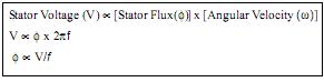
This makes constant V/f the most common speed
control of an induction motor.
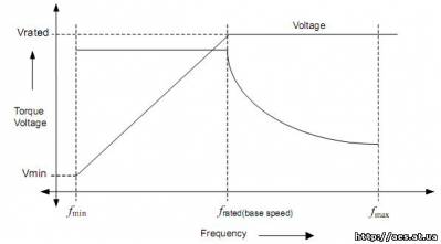
Figure 3 shows the relation between the voltage and
torque versus frequency. Figure 3 demonstrates volt-
age and frequency being increased up to the base
speed. At base speed, the voltage and frequency reach
the rated values as listed in the nameplate. We can
drive the motor beyond base speed by increasing the
frequency further. However, the voltage applied cannot
be increased beyond the rated voltage. Therefore, only
the frequency can be increased, which results in the
field weakening and the torque available being
reduced. Above base speed, the factors governing
torque become complex, since friction and windage
losses increase significantly at higher speeds. Hence,
the torque curve becomes nonlinear with respect to
speed or frequency.
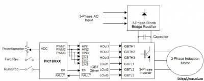
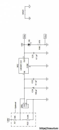
IMPLEMENTATION
Power
Standard AC supply is converted to a DC voltage by
using a 3-phase diode bridge rectifier. A capacitor fil-
ters the ripple in the DC bus. This DC bus is used to
generate a variable voltage and variable frequency
power supply. A voltage source power inverter is used
to convert the DC bus to the required AC voltage and
frequency. In summary, the power section consists of a
power rectifier, filter capacitor, and power inverter.
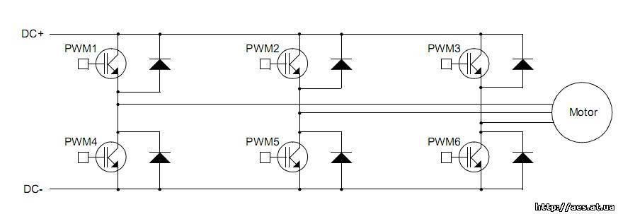
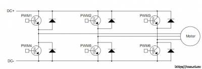
The motor is connected to the inverter as shown in
Figure 4. The power inverter has 6 switches that are
controlled in order to generate an AC output from the
DC input. PWM signals generated from the micro-
controller control these 6 switches. The phase voltage
is determined by the duty cycle of the PWM signals. In
time, a maximum of three switches will be on, either
one upper and two lower switches, or two upper and
one lower switch.
When the switches are on, current flows from the DC
bus to the motor winding. Because the motor windings
are highly inductive in nature, they hold electric energy
in the form of current. This current needs to be dissi-
pated while switches are off. Diodes connected across
the switches give a path for the current to dissipate
when the switches are off. These diodes are also called
freewheeling diodes.
Upper and lower switches of the same limb should not
be switched on at the same time. This will prevent the
DC bus supply from being shorted. A dead time is given
between switching off the upper switch and switching
on the lower switch and vice versa. This ensures that
both switches are not conductive when they change
states from on to off, or vice versa.
Control
To derive a varying AC voltage from the power inverter,
pulse width modulation (PWM) is required to control the
duration of the switches’ ON and OFF times. Three
PWMs are required to control the upper three switches
of the power inverter. The lower switches are controlled
by the inverted PWM signals of the corresponding
upper switch. A dead time is given between switching
off the upper switch and switching on the lower switch
and vice versa, to avoid shorting the DC bus.
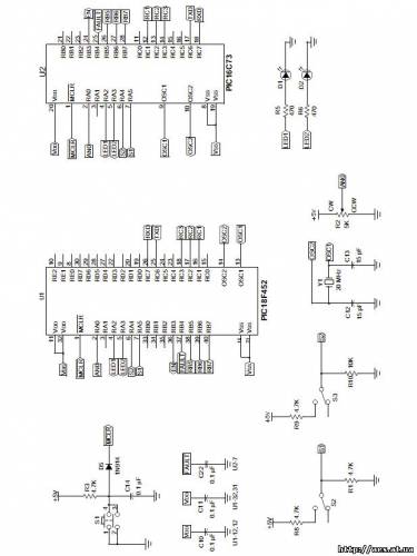
PIC18XXX2 has two 10-bit PWMs implemented in the
hardware. The PWM frequency can be set using the
PR2 register. This frequency is common for both
PWMs. The upper eight bits of duty cycle are set using
the register CCPRxL. The lower two bits are set in
CCPxCON<5:4>. The third PWM is generated in the
software and output to a port pin.
SOFTWARE PWM IMPLEMENTATION
Timer2 is an 8-bit timer used to control the timing of
hardware PWMs. The main processor is interrupted
when the Timer2 value matches the PR2 value, if a cor-
responding interrupt enable bit is set.
Timer1 is used for setting the duty cycle of the software
PWM (PWM3). In the Timer2 to PR2 match Interrupt
Service Routine (ISR), the port pin designated for
PWM3 is set to high. Also, the Timer1 is loaded with the
value which corresponds to the PWM3 duty cycle. In
Timer1 overflow interrupt, the port pin designated for
PWM3 is cleared. As a result, the software and
hardware PWMs have the same frequency.
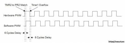
The software PWM will lag by a fixed delay compared
to the hardware PWMs. To minimize the phase lag, the
Timer2 to PR2 match interrupt should be given highest
priority while checking for the interrupt flags in the ISR.
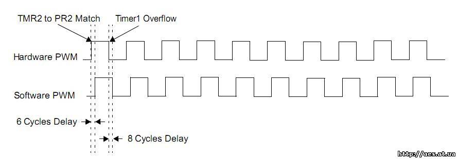
The ISR has a fixed entry latency of 3 instruction
cycles. If the interrupt is due to the Timer2 to PR2
match then it takes 3 instruction cycles to check the flag
and branch to the code section where the Timer2 to
PR2 match task is present. Therefore, this makes a
minimum of six instruction cycles delay, or phase shift
between the hardware PWM and software PWM, as
shown in Figure 5.
The falling edge of software PWM trails the hardware
PWM by 8 instruction cycles. In the ISR, the TMR2 to
PR2 match has a higher priority than the Timer1 over-
flow interrupt. Thus, the control checks for TMR2 to
PR2 match interrupt first. This adds 2 instruction cycles
when the interrupt is caused by Timer1 overflow, mak-
ing a total delay of 8 instruction cycles. Figure 5 shows
the hardware PWM and PWM generated by software
for the same duty cycle.
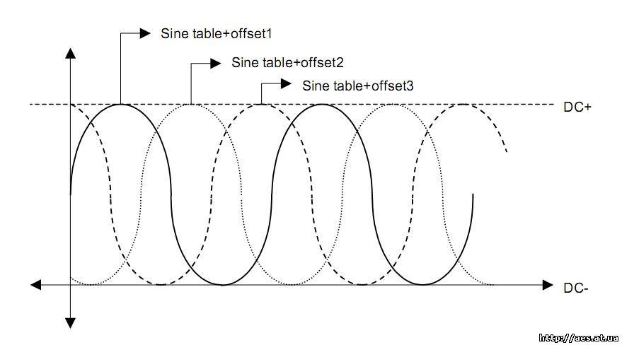
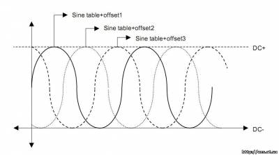
A sine table is created in the program memory, which is
transferred to the data memory upon initialization.
Three registers are used as the offset to the table. Each
of these registers will point to one of the values in the
table, such that they will have a 120 degrees phase
shift to each other as shown in the Figure 6. This forms
three sine waves, with 120 degrees phase shift to each
other.
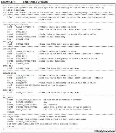
After every Timer0 overflow interrupt, the value pointed
to by the offset registers on the sine table is read. The
value read from the table is scaled based on the motor
frequency input, by multiplying by the frequency input
value to find the ratio of PWM, with respect to the max-
imum DC bus. This value is loaded to the correspond-
ing PWM duty cycle registers. Subsequently, the offset
registers are updated for next access. If the direction
key is set to the motor to reverse rotation, then PWM1
and PWM2 duty cycle values are loaded to PWM2 and
PWM1 duty cycle registers, respectively. Typical code
section of accessing and scaling of the PWM duty cycle
is as shown in Example 1.
The three PWMs are connected to the driver chip
(IR21362). These three PWMs switch the upper three
switches of the power inverter. The lower switches are
controlled by the inverted PWM signals of the corre-
sponding upper switch. The driver chip generates
200 ns of dead time between upper and lower switches
of all phases.
A potentiometer connected to a 10-bit ADC channel on
the PICmicro microcontroller determines the motor
speed. The microcontroller uses the ADC results to cal-
culate the duty cycle of the PWMs and thus, the motor
frequency. The ADC is checked every 2.2 milliseconds,
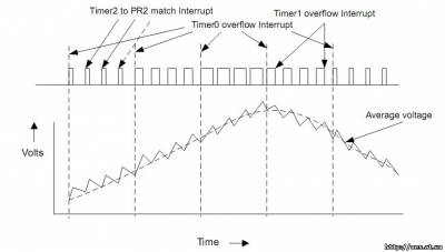
which provides smooth frequency transitions. Timer0 is
used for the timing of the motor frequency. The Timer0
period is based on the ADC result, the main crystal fre-
quency, and the number of sine table entries. New
PWM duty cycles are loaded to the corresponding duty
cycle registers during the Timer0 overflow Interrupt
Service Routine. So, the duty cycle will remain the
same until the next Timer0 overflow interrupt occurs, as
shown in Figure 7.
EQUATION 4: 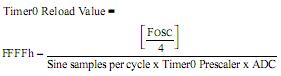
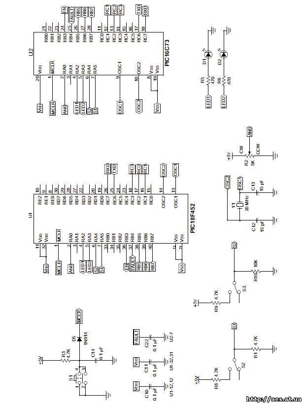
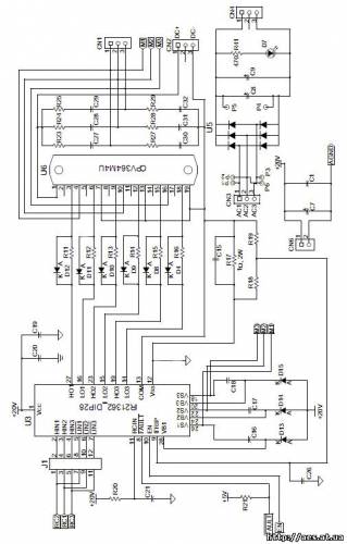
System Overview
Figure 8 shows an overall block diagram of the power
and control circuit. A potentiometer is connected to AD
Channel 0. The PICmicro microcontroller reads this
input periodically to get the new speed or frequency ref-
erence. Based on this AD result, the firmware deter-
mines the scaling factor for the PWM duty cycle. The
Timer0 reload value is calculated based on this input to
determine the motor frequency. PWM1 and PWM2 are
the hardware PWMs (CCP1 and CCP2). PWM3 is the
PWM generated by software. The output of these three
PWMs are given to the higher and lower input pins of
the IGBT driver as shown in Figure 8. The IGBT driver
has inverters on the lower input pins and adds dead-
time between the respective higher and lower PWMs.
This driver needs an enable signal, which is controlled
by the microcontroller. The IGBT driver has two FAULT
monitoring circuits, one for over current and the second
for under voltage. Upon any of these FAULTS, the out-
puts are driven low and the FAULT pin shows that a
FAULT has occurred. If the FAULT is due to the over
current, it can be automatically reset after a fixed time
delay, based on the resistor and capacitor time
constant connected to the RCIN pin of the driver.
The main 3-phase supply is rectified by using the
3-phase diode bridge rectifier. The DC ripple is filtered
by using an electrolytic capacitor. This DC bus is
connected to the IGBTs for inverting it to a V/f supply.
FIGURE 8: BLOCK DIAGRAM OF 3-PHASE INDUCTION MOTOR CONTROL
CONCLUSION
To control the speed of a 3-phase induction motor in
open loop, supply voltage and frequency need to be
varied with constant ratio to each other. A low cost solu-
tion of this control can be implemented in a PICmicro
microcontroller. This requires three PWMs to control a
3-phase inverter bridge. Many PICmicro micro-
controllers have two hardware PWMs. The third PWM
is generated in software and output to a port pin.
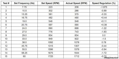
Above tests are conducted on the motor with the following specifications:
• Terminal voltage: 208-220 Volts
• Frequency: 60 Hz
• Horsepower: ? HP
• Speed: 1725 RPM
• Current: 2.0 Amps
• Frame: 56 NEMA
APPENDIX C: GLOSSARY
Air Gap
Uniform gap between the stator and rotor.
Angular Velocity
Velocity in radians (2? x frequency).
Asynchronous Motor
Type of motor in which the flux generated by the stator
and rotor have different frequencies.
Base Speed
Speed specified on the nameplate of an induction
motor.
Break Down Torque
Maximum torque on the speed-torque characteristics
at approximately 80% of base speed.
EMF
Electromotive Force. The potential generated by a cur-
rent carrying conductor when it is exposed to magnetic
field. EMF is measured in volts.
Full Load Torque
Rated torque of the motor as specified on the
nameplate.
IGBT
Insulated Gate Bipolar Transistor.
Lenz’s Law
The Electromotive force (EMF) induced in a conductor
moving perpendicular to a magnetic field tends to
oppose that motion.
Locked Rotor Torque
Starting torque of the motor.
Pull-up Torque
Torque available on the rotor at around 20% of base
speed.
Rotor
Rotating part of the motor.
Slip Speed
Synchronous speed minus base speed.
Stator
Stationary part of the motor.
Synchronous Motor
Type of motor in which the flux generated by the stator
and rotor have the same frequencies. The phase may
be shifted.
Synchronous Speed
Speed of the motor corresponding to the rated
frequency.
Torque
Rotating force in Newton-Meters or Pound-Inches.
Скачать исходники кода
Скачать [294,67 Kb] (cкачиваний: 35) статью в оригинале
|